Professional Plastic Pipe Fitting Mould Manufacturer With 20 Years Of Experience - Spark Mould



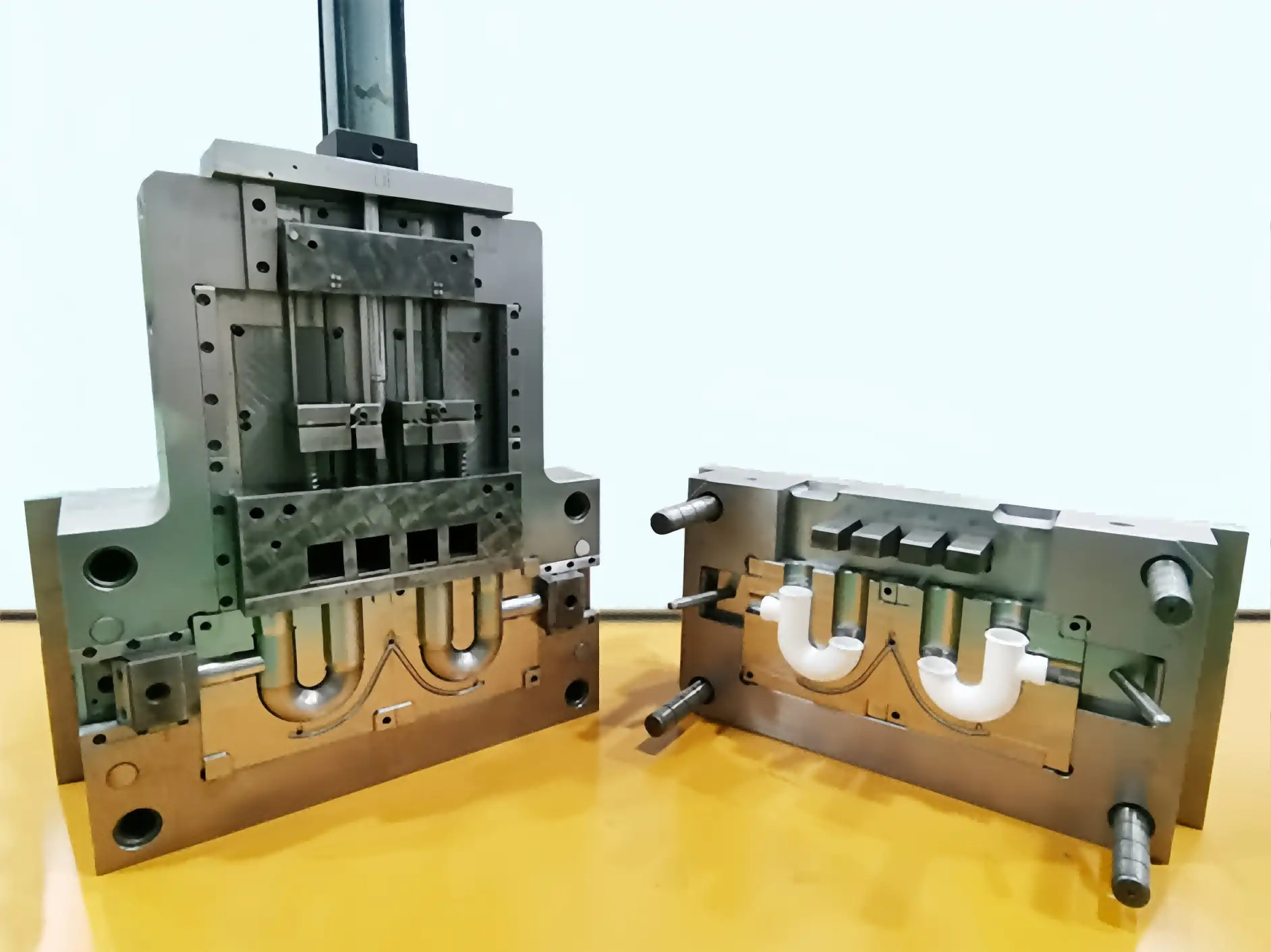
The Collapsible Core Injection Mold Solution is Used For The J Bend Made of PP Material
Project Specifications & Part Anatomy
| Parameter | Technical Specification |
| Part Name | 1-1/2" PP J-Bend Pipe Fitting with Side Inlet |
| Resin Material | Polypropylene (PP) – Homopolymer / Impact Copolymer |
| Cavitation | 2-Cavity |
| Runner System | Cold Runner System |
| Gating Type | Cavity-Side Subsurface Gate (Front-Mold Tunnel Gate) |
| Main 180° Core System | Collapsible Core (6 Arc Segments + Steel Cable) |
| Side Inlet Core System | Angle Pin (Cam Pin) & Slide Block Mechanism |
| Hydraulic Actuation | Single Hydraulic Cylinder Synchronizing 2 Cavities |
Tooling Engineering Deep-Dive: Core-Pulling Architecture
1.The 180° Articulated Segmented Chain Core (Collapsible Core)
A standard straight core pin cannot demold a 180° curved tubular geometry. Instead of relying on bulky gear-driven rotational mechanisms, this mold utilizes a segmented articulated chain core mechanism:
- 6-Segment Arc Geometry: The 180-degree core section is precision-machined and sliced into 6 distinct interlocking arc segments.
- Rigid Under Injection Pressure: When fully advanced along dual precision guide rails, the segments lock together, forming a rigid, seamless 180° solid core that withstands high injection pressures without flashing or core deflection.
- Smooth Flexible Retraction: Guided by high-tensile steel wire ropes (cables) and dual linear guide rails, the 6 segments flex and articulate during demolding, pulling smoothly along the inner curve of the PP pipe.
- Synchronized Actuation: A single heavy-duty hydraulic cylinder drives the core-pulling mechanism for both cavities simultaneously. This ensures balanced mechanical loading, simplifies mold maintenance, and maintains a highly compact mold size.
2. Why Segmented Chain Cores Beat Rotational Mechanisms for J-Bends
Elimination of Gear Backlash: Traditional rack-and-pinion unscrewing cores for curved fittings are prone to mechanical backlash and wear, often leading to mismatch lines inside the pipe wall.
- Space & Tooling Envelope: Articulated chain cores require significantly less space than large circular rotational racks, allowing a compact 2-cavity layout within a standard injection molding machine (IMM) tie-bar envelope.
- Lower Maintenance Cost: By minimizing rotating gears and bearings inside the mold base, tool downtime for lubrication and mechanical resets is reduced by over 35%.
3. Side Inlet Core Pulling: Angle Pin & Slide Mechanism
The extension tube of the J-Bend features a threaded side inlet for secondary branch drainage connections.
Because this side feature is perpendicular to the main parting line, it is released using a robust angle pin (horn pin) and slide block mechanism.
As the mold opens, the angled cam pin drives the slide block outward, freeing the external/internal thread undercut before the main part ejection sequence begins.
Gating & Runner Strategy: Cavity-Side Subsurface Gate
To maximize production automation and lower per-part labor costs, the mold employs a Cavity-Side Subsurface Gate (Front-Mold Tunnel Gate):
- Automatic Degating: During the mold opening stroke, the geometry of the subsurface tunnel gate automatically shears the cold runner from the molded J-Bend.
- Zero Manual Trimming: Parts fall onto the conveyor belt completely severed from the runner system, eliminating the need for operators to manually trim gates and preventing accidental surface gouging on the visible pipe exterior.
- Optimized Flow for Polypropylene: PP has excellent melt flowability. Placing the subsurface gate on the cavity side ensures a balanced fill into the thick walls of the 1-1/2" fitting while concealing the vestige mark in an aesthetically low-impact zone.
Mold Structure & Working Action – Step by Step
- The submarine gate automatically breaks off from the part as the two halves separate.
- The angle pin withdraws the side-outlet slider laterally, freeing the threaded port.
- Simultaneously (or slightly delayed), the hydraulic cylinder activates, collapsing the 6-segment core and retracting it from the J-Bend.
- Ejection: Ejector pins or a stripper plate push the finished J-Bends off the straight outer core remaining on the B-side.
- Return cycle: Hydraulic cylinder resets the foldable core; slider returns with wedge locking; mold closes for next shot.
Alignment & precision:
Guide rails for the segmented core are CNC-ground and located with tapered interlocks when the core is fully extended. This guarantees roundness and repeatability within 0.05 mm over the 180° arc. Interchangeable segment sets allow for easy maintenance.
Conclusion
This 2-cavity cold-runner mold for a 1-1/2 inch PP J-Bend with side outlet exemplifies how integrating a foldable chain core and a front-mold submarine gate solves multi-axis complexity in a lean, reliable manner. While the inability to directly water-cool the articulated core calls for external thermal management, the overall gains in automation, footprint, and part quality far outweigh this limitation. It’s a textbook case of designing for manufacturability without over-engineering.