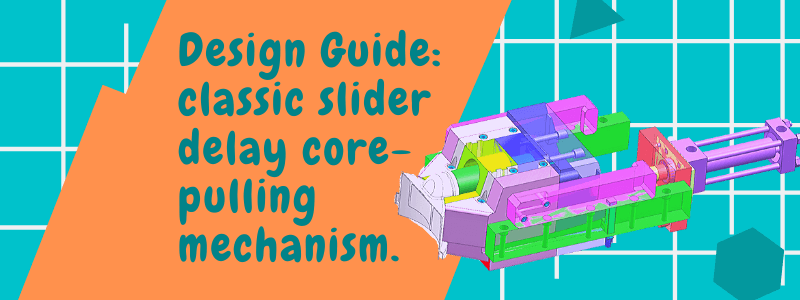
In the design of injection molds, a slider mechanism is often applied to the slider. This mechanism is called the slider core-pulling delay mechanism.
The slider core-pulling mechanism is often used in the following two aspects:
I. Handling core pulling mechanism with large packing force.
2. The core-pulling mechanism has an undercut, which needs to be completed by second core-pulling.
4 common methods.
The mechanism needs to design the slider delay. The following four methods are commonly used:
1. Spring delay.
2. Delay stop (wedge to make a straight delay).
3. Mechanical stopper.
4. Use the oil cylinder as a stopper.
Note:
1.The spring delay is suitable for large clamping force or small slider. When the spring is used for a certain life, it will cause strength fatigue and risk of failure. Therefore, it is necessary to regularly check the use of the spring and replace it.
2.Some large sliders can ensure the safe and reliable core-pulling sequence through delay stopper or mechanical stopper.
3.Most important thing. The second movement of the slider must be safe and reliable. Otherwise it will strain the product.
Classic slider core pulling mechanism.
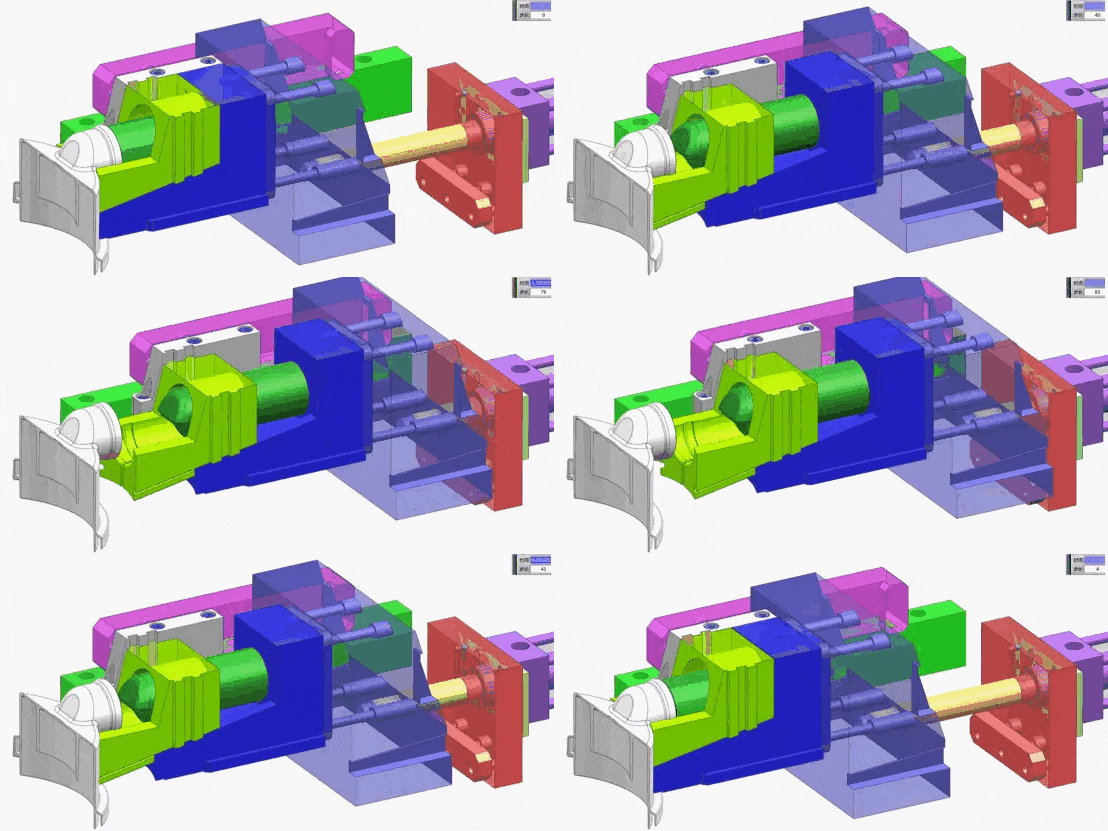
The figure below is a group of delayed core-pulling structures with mechanical stops, which are very practical.
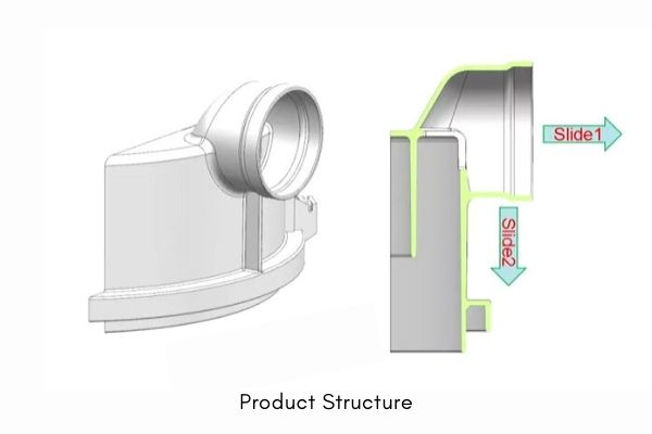
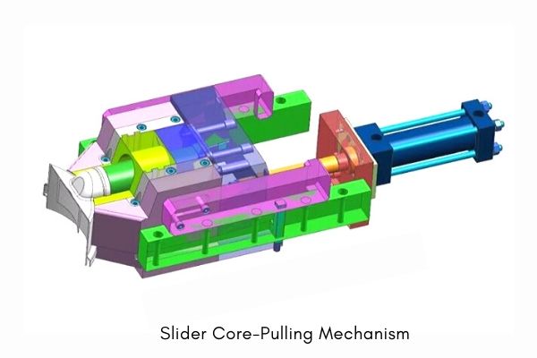
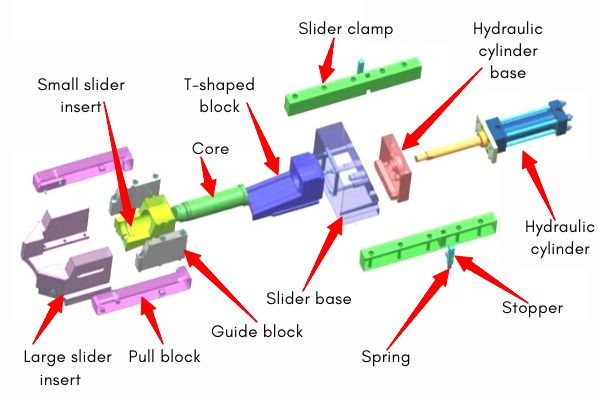
Structural principle of delayed core pulling mechanism.
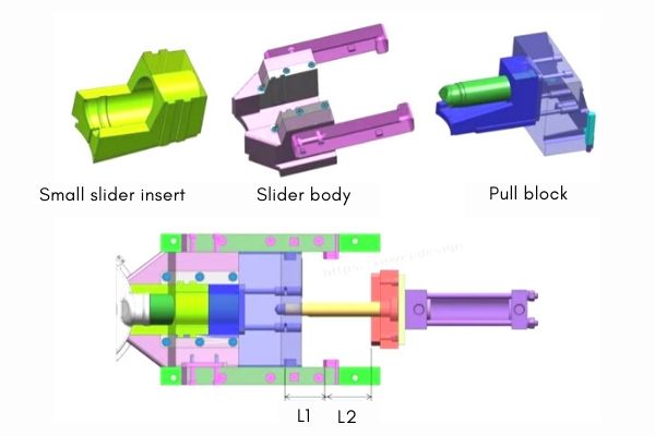
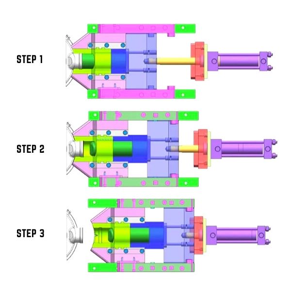
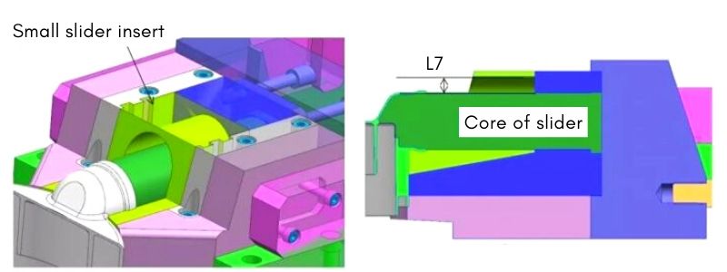
After opening the mold, the main body of the pull block moves backwards under the driving of the oil cylinder. The small slider insert retracts downward. Draw out the buckle on the product slot. At the same time, the slider body remains stationary under the action of the stop.
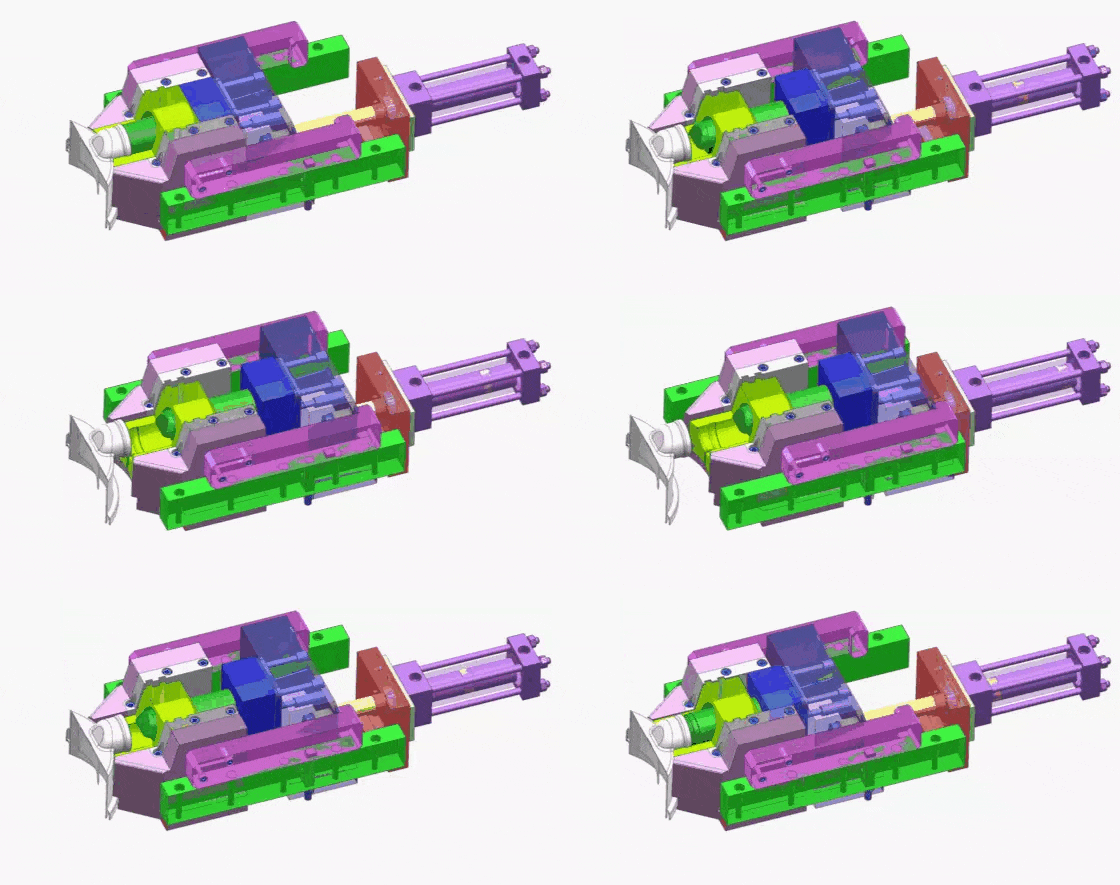
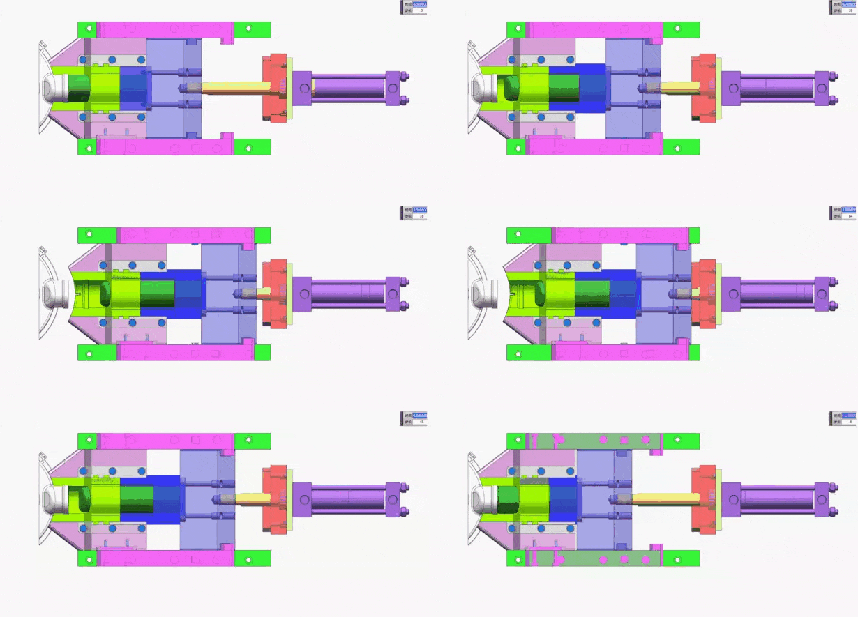
When the main body of the block travels a distance of L1. The small slider inserts have all come off the undercuts of the product. The first core pulling is completed. At the same time, the stopper moves backwards.The pull block pulls the slider body. The second core draw begins. The oil cylinder continues to drive, and the sliding position moves L 2 distance as a whole, completely detaching from the product.
Principle of the first core pulling and design guiding mechanism.
The first core pulling principle is driven by an inclined T-slot. It is the same as the ordinary slider drawing, and it is understood according to the wedge and slider design. The direction of the guide groove is the same as the direction of disengaging the undercut.
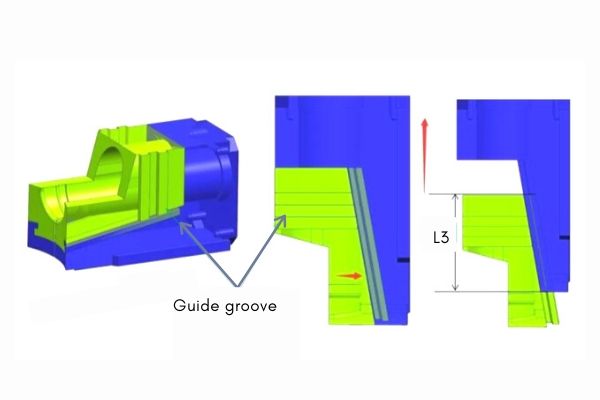
Requires attention:
1. The small slider cannot completely disengage from the inclined T-slot. The length L 3 must have a pipe position of at least 1/2 to facilitate resetting.
2. In addition, the clearance height L 7 of the slider core should be greater than the distance that the small slider insert moves downward. This prevents interference.
How to design slider delay?
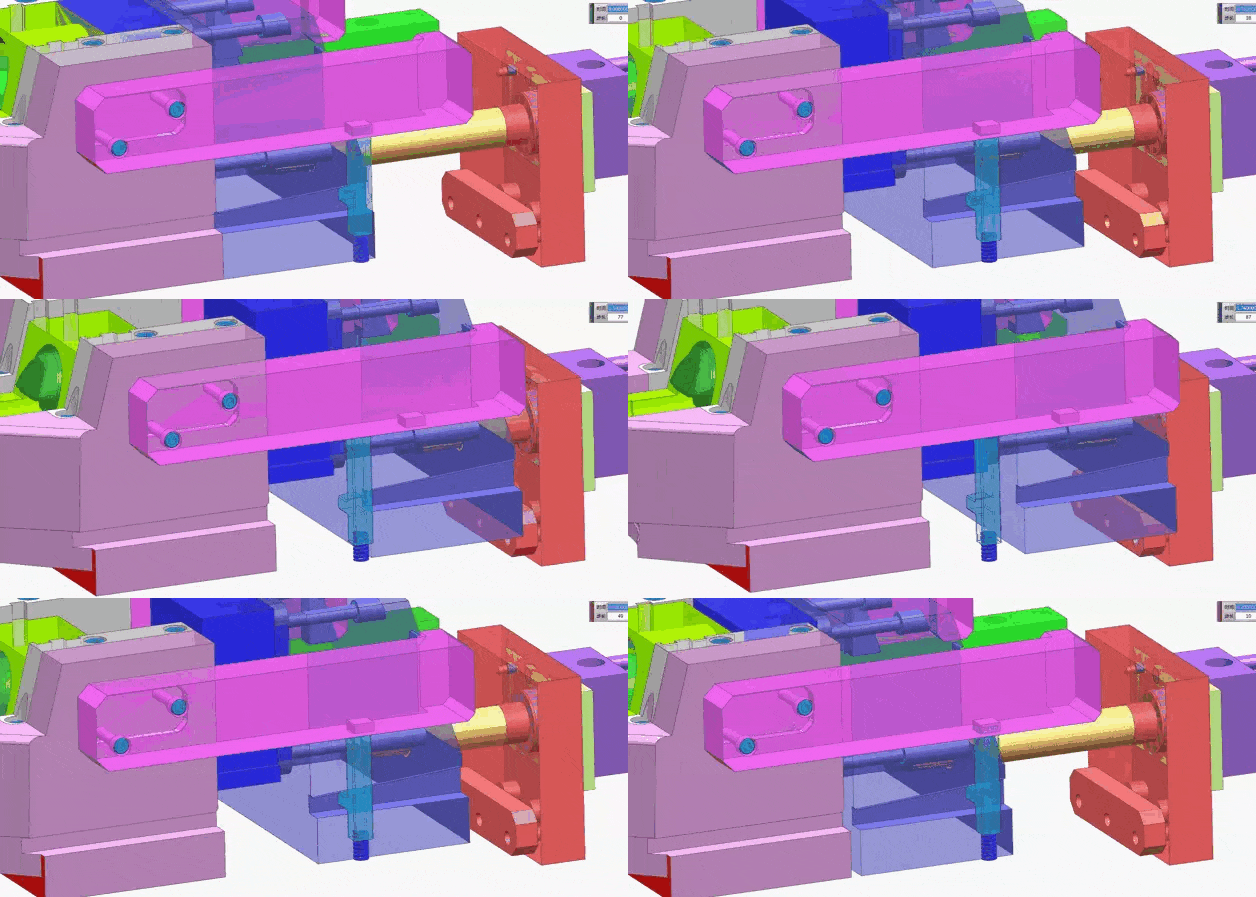
This structure adopts the “stopper + chute + spring” delay design structure. The design of the block plus the chute is to delay the return of the large slider. The “stopper + spring” is used to reset the stopper.
It should be noted that L 5 is greater than L 4 and L 6. Make sure that the stop does not interfere with the pull block and the slider seat.
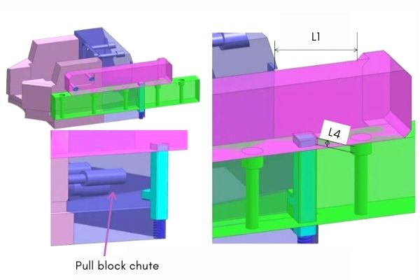
How does the second core pulling mechanism move together?
The design pull block is fixed on the large slider. After the moving distance L1 of the pull block body, the pull block is driven to drive the slider base. Realize second core pulling.
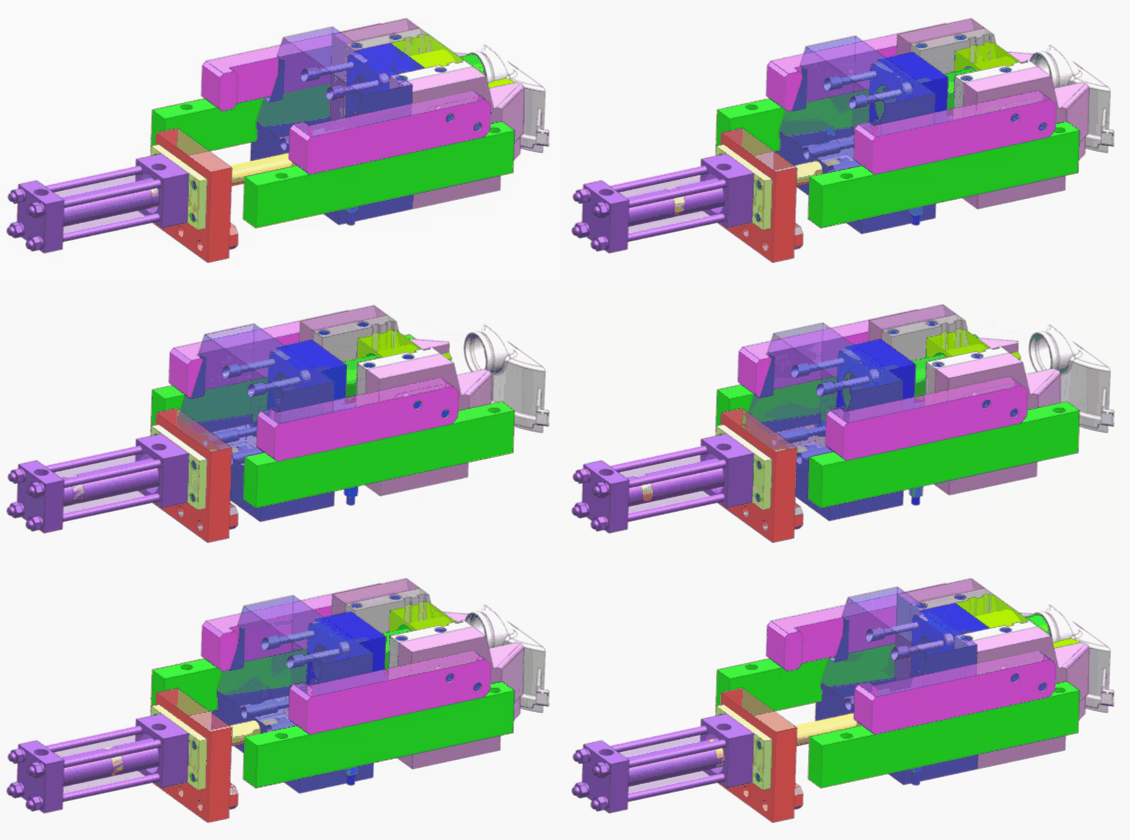
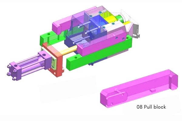
How to reset the core pulling mechanism?
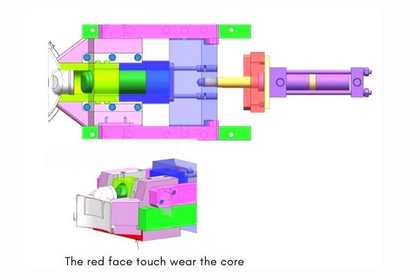
When clamping the mold, the block body first pushes the slider body to reset. When large slider insert (red face) wear the core, the slider body is completely reset. The block body continues to move, pushing the small slider insert to reset. At the same time, the stopper also starts to reset until the mold clamping is completed.
Note: The slider body must be reset first. The small slider insert can be reset.
At the end.
To master this structure, there are 5 points to be solved:
1.Principle of second core pulling.
2. The first core pulling principle and the design of the guide mechanism.
3. Delay design of slider.
4. Second core pulling motion.
5. Reset by core pulling twice.
Solve 5 key points, the secondary core pulling structure of the slider becomes simpler for you.
If you want to know about other core pulling mechanisms, please read the following article.
7 design tips on the side core pulling mechanism of the injection mold
How to design an injection mold for 90 degree elbow
