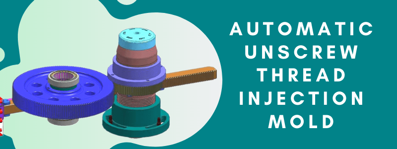
There are two types of threads on plastic parts: external threads and internal threads. External threads with low accuracy generally use lateral core-pulling mechanism. The internal thread has two structures: forced ejection and automatic ejection.
Mass production of threaded cover requires automatic unscrew thread injection molds. This article introduces the automatic unscrew thread structural design of the screw cap. Let’s dive in together.
Threaded cover product analysis.
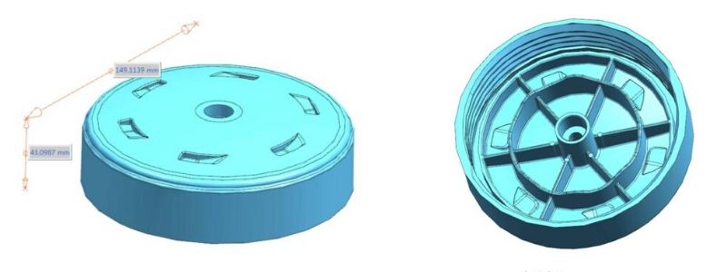
The size of this thread cover is larger. The product has a diameter of 149.11mm and a height of 43.09mm. Because the product size is large, the mold only has one cavity. The product picture is shown below.
Thread mold gate system.
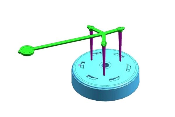
Three-point inlet into the fine nozzle. Because of the large size of the product, this design is needed. Because the material flow is more uniform, the product denaturation is relatively small. Round products usually use this gate design.
The overall structure of the mold.
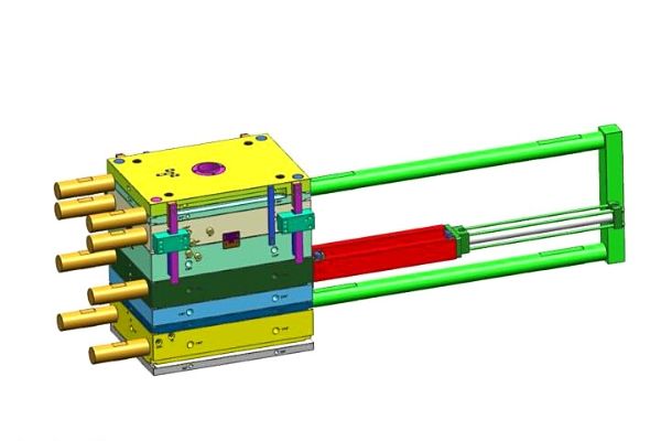
The overall size of this mold is: 550mmX750X816mm. The three-plate mold structure is a medium-sized mold. As shown below.
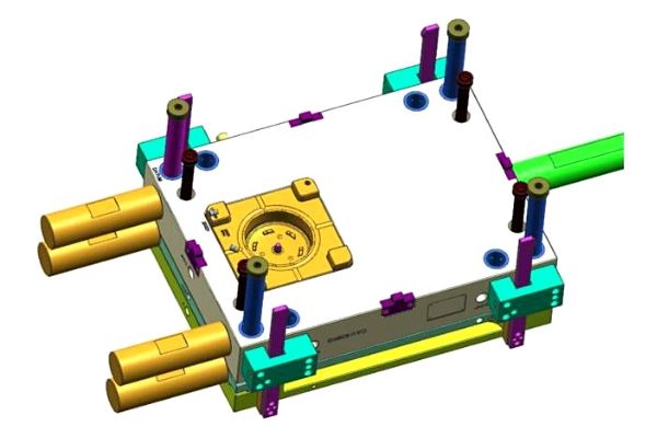
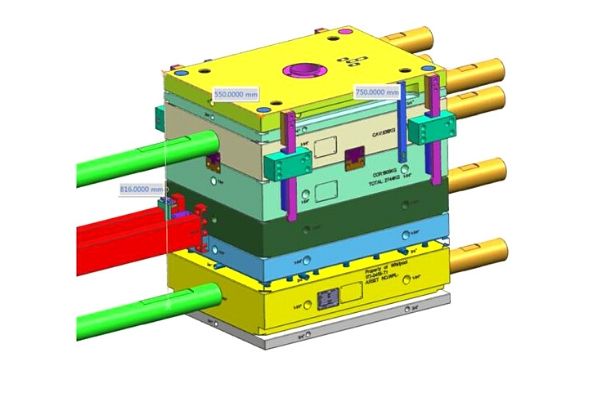
Threaded structural accessories.
The thread part adopts the automatic unscrew thread structure, which is realized by the rotation of the gear driven by the oil cylinder. As shown below.
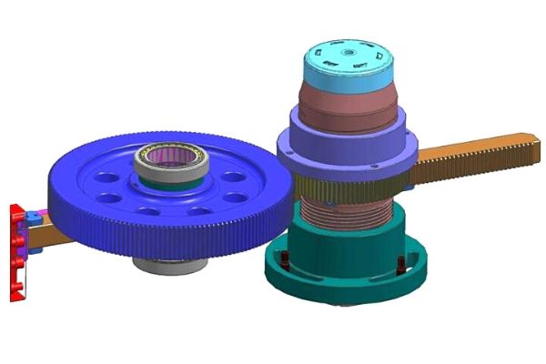
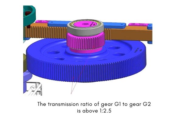
The structural accessories of the thread are shown below. The thread-removing mechanism adopts the “rack + gear” mechanism. The oil cylinder drives the rack, the rack drives the main gear G1, and the main gear G1 drives the large gear G2. The large gear G2 drives the main shaft gear G3 to rotate. To achieve automatic thread ejection of the product.
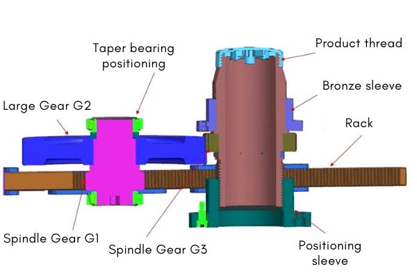
Design details of threaded structural parts.
Thread distance.
The product is right-handed double-ended thread. Tooth pitch = lead / head number. Number of retracted teeth required: total stroke/pitch +0.5.
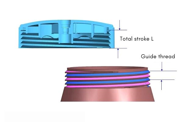
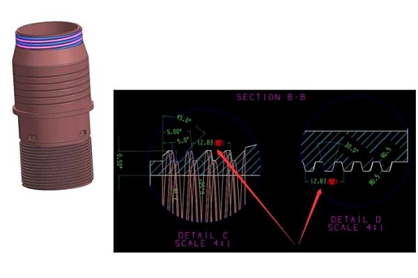
Screw pitch.
The retraction pitch of the tooth axis should be the same as that of the product, and the angle can be different.
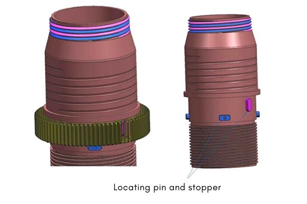
Locating pin and stopper.
The positioning pin is used to fix the dental shaft and the gear. The positioning pin can ensure the synchronous rotation of the dental shaft and the gear, but it cannot prevent the gear from falling down, so a block must be designed.
Gear ratio.
The transmission ratio of the main shaft gear G1 and the large gear G2 is preferably above 1:2.5, so that the smaller the driving force of the oil cylinder is, the smaller the transmission ratio.
3 functions of the positioning sleeve.
1. Support the dental shaft and withstand the injection pressure.
2. The product thread retreats back against the inner belt of the dental burr. If it does not, it will only rotate in place.
3. Adjust the height of the dental shaft, and adjust the height and tightness through the three U-shaped grooves behind the tooth. After adjusting it, fix it with a constant-height screw. It is not easy to loosen the screw with a washer.
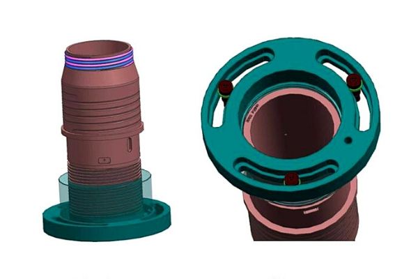
Cooling system.
The products on the rear mold side are cooled by double rotating water transport.
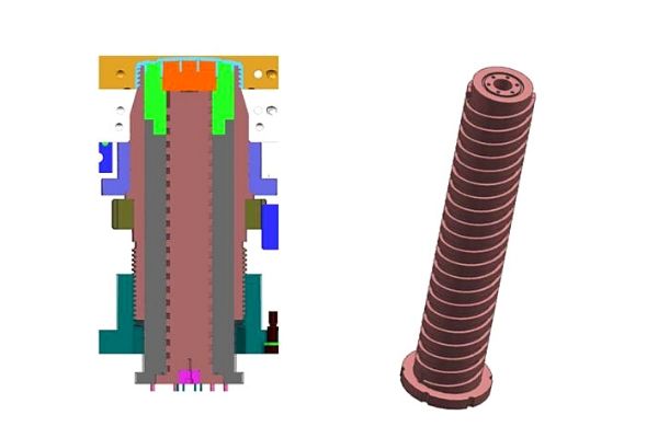
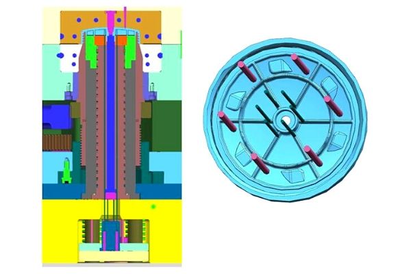
Ejection system.
The thimble ejects the product, and the arrangement of thimble is shown.
Conclusion.
Most automatic unscrew thread injection molds are multi-cavity molds. Excluding larger-sized threaded plastic parts. Multi-cavity threaded injection mold means more mechanisms. This threaded lid mold is relatively simple. The complex thread mechanism can be expanded by referring to this article.
