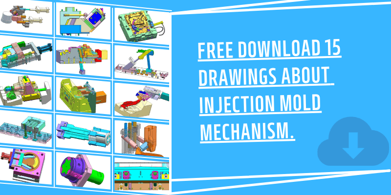
Free Download 15 Drawings About Injection Mold Mechanism
Here are 15 drawings of injection mold mechanism about sliders and lifter. These are free resources that are great for beginners. You can download mold mechanism drawings for free. There is a download link at the end of the article. Below is the list:
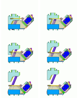
#1 Angle Pin Drive Slider Injection Mold Mechanism.
Affected by the size of the mold, the angle pin can only be used in some molds with small lateral dimensions and no undercut structure. But it can reduce mold opening steps, and mold opening and parting can be carried out at the same time.
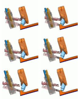
#2 Oblique Core Pulling Mechanism
Use helical teeth to engage the slider to pull the core diagonally. Core pulling and mold opening can be carried out simultaneously, shortening the time.
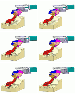
#3 Slider drive slider Injection Mold Mechanism
T-slots with different slopes are arranged between the 3 sliders. The lateral movement of the oil cylinder is used to achieve core pulling in two directions.
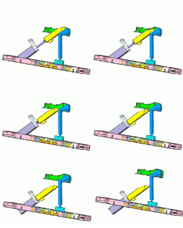
#4 “Uphill” lifter Injection Mold Mechanism.
In the injection mold mechanism, the lifters is used to form the internal undercut mechanism of the product. Suitable for relatively simple undercut situations.
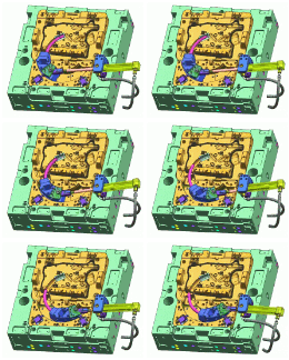
#5 Arc core pulling mechanism
The plastic elbow will use the arc core pulling mechanism. The slider is driven by the oil cylinder to make a circular motion.
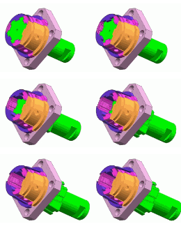
#6 Injection Mold Mechanism Collapsible Core.
This core pulling mechanism is composed of multiple sliders. When pulling the core, first shrink the slider inward and then pull it out. It is used to solve the molding of flaring, internal thread and other parts.
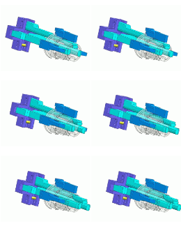
#7 Lifter Ejector Mold Mechanism
There is a hole on the side of the plastic part, which is solved by the lifter mechanism.When the mold is open, the inclined top vertically ejects the product for a certain distance until the limit block, and the lifter shrinks inward and leaves the hole.
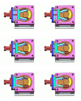
#8 Arc Core Pulling Mechanism
The mold structure is similar to the pipe injection mold mechanism. The oil cylinder drives two tie rods to pull the slider to make an arc movement.
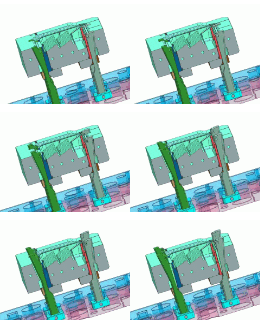
#9 Lifter Ejection Mold Mechanism
Similar to #7 mold mechanism. When the mold is opened, the lifter will be pushed out a certain distance from the product and reach the limit position, and the lifter will tilt to one side and separate from the product.

#10 Collapsible Core Mechanism 2
The angle pin drives the slider to pull out the inner core, and the outer core first shrinks inward, and then the whole is withdrawn from the product. Similar to #6 mold mechanism.
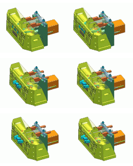
#11 Lifter And Slider Injection Mold Mechanism
When the mold is opened, the oil cylinder controls the yellow slider to move backward, and the lifter moves laterally in the middle of the slider. Reach the limit, and then withdraw as a whole.
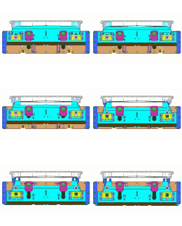
#12 Delay Slide Core Pulling Mechanism
There are undercuts on both ends of the plastic part. Set up 4 sliders similar to the lifter. When the bottom large slider moves down, the inner blue slider shrinks inward to achieve core pulling.
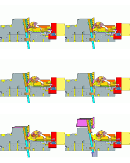
#13 Arc Core Pulling Mechanism And Lifter.
When the mold is opened, the oil cylinder pulls the slider at the buckle position to make a circular motion through the connecting rod. When it reaches the limit, it is pulled out as a whole. The product is pushed out outwards, and the lifter is tilted inwardly and detached at the same time.
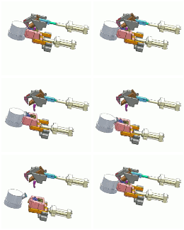
#14 Movable Mold Cylinder Oblique Core Pulling.
Before opening the mold, the oil cylinder drives the slider to pull the core diagonally. When the mold is opened, the movable mold wedge block drives the rear mold small slider to pull out backward. Then through the rear mold cylinder to withdraw as a whole.
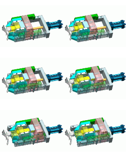
#15 Delay Slider Core Pulling Mechanism
When the mold is opened, the oil cylinder drives the red slider to slide. At the same time, the red slider is lifted upwards, forcing the cylinder to press down on the bottom slider to separate from the product. When it reaches the limit, it is withdrawn as a whole.
The following is a file download list of 15 mold institutions. You will get the .X_T file for each mold mechanism. These documents are only used for technical exchanges and not for commercial use.
