
Contradictions may arise when selecting a gate design. Comprehensive consideration and flexibility should be based on actual conditions and experience. Gate location is one of the key factors in product quality.
1.Consider the shape and structure of the plastic part.
The gate is set according to the geometry and structure of the product. It should be placed in a location that is easy to understand and does not affect the appearance of the plastic part.
The gate should be placed on the assembly surface. Avoid asking for a higher surface. The number of gates requires CAE flow analysis.
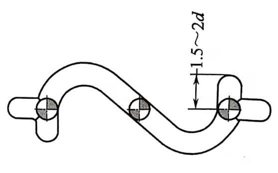
2.Avoid jetting phenomena.
The melt directly injects the core to bend the core. It also has an effect on the mold insert. The melt flows into the cavity or core curved flow. Avoid jetting phenomena. As figure show:
3.Avoid the retention effect of the melt.
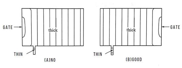
When the molten material enters a region where the wall thickness varies greatly. The front edge of the thin-walled area will slow down or even stagnate. Until the thick wall is full. Such a gate design can cause sink marks on the surface of the plastic part.
As the picture shows. The gate is set at the maximum wall thickness.
4.Avoid plastic molding difficulties.
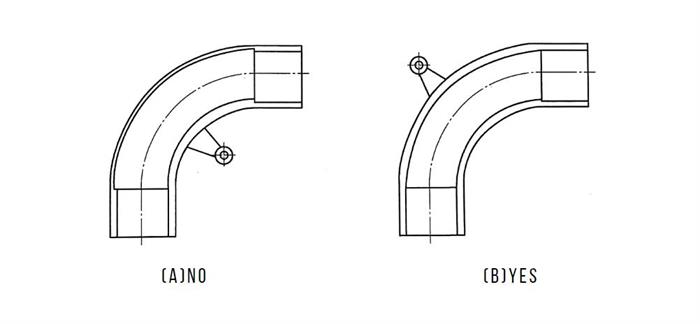
Take the 90° pipe mold as an example. AS figure A. Set the gate position on the inside of the elbow. The purpose is to make the gate position of the mold consistent with the center of the mold to avoid the gate offset of the mold. But the test results show that. Since the curved core is subjected to the injection force, the core is pushed to the opposite side, so that the pipe cannot be molding. Set the gate position on the back of the elbow. As figure B.
5.The location of the gate should be avoid the flow ratio is too large.
The number and location of the gates should satisfy the maximum flow length/wall thickness ratio. Avoid filling the cavity difficult. The melt process should be minimized and flow direction changes minimized to reduce energy loss.
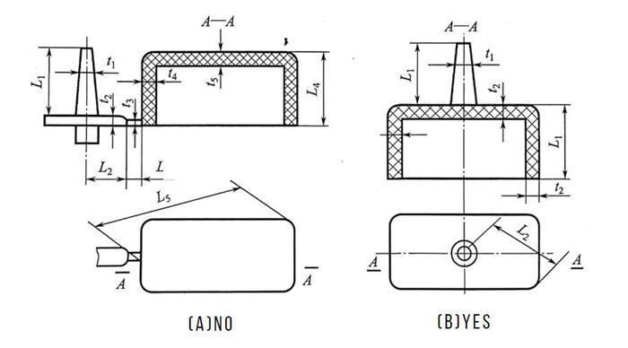
As shown in Figure (a). The process L5 is long, the flow direction changes a lot, and the filling condition is poor. It is not conducive to exhaust. It often causes defects such as lack of material or bubbles at the top of the product.
Figure (b) shows the direct gate and the process L2 is short.
This table is the allowable value of the common plastic flow ratio for design reference.
| Material | Injection pressure/MPa | Flow Ratio | Material | Injection pressure/MPa | Flow Ratio |
|---|---|---|---|---|---|
| Polyethylene | 150 | 250~280 | Hard polyvinyl chloride | 130 | 130~170 |
| Polyethylene | 60 | 100~140 | Hard polyvinyl chloride | 90 | 100~140 |
| Polypropylene | 120 | 280 | Hard polyvinyl chloride | 70 | 70~140 |
| Polypropylene | 70 | 200~240 | Soft polyvinyl chloride | 90 | 100~280 |
| Polystyrene | 90 | 280~300 | Soft polyvinyl chloride | 70 | 100~240 |
| Polyamide | 90 | 200~360 | Polycarbonate | 130 | 120~180 |
| POM | 100 | 110~210 | Polycarbonate | 90 | 90~130 |
6.The gate setting requires an injection pressure balance within the mold cavity.
Each corner of the cavity can be filled with molten material at the same time. The plastic is melted at the optimum temperature.
7.Avoid setting the gate at thin wall of plastic parts.
The gate position should be placed at the thickest part of the wall thickness of the product to facilitate the feeding of the melt. Reduce the microcosm produced by the product, shrink the hole.
8.Avoid setting the gate at a location that is not conducive to gas removal.
For example, the gating system of the part is designed as a side gate. The product trapped gas. The gating system should be changed to a point gate. Feeding from the top facilitates venting and feeding. The mold should not be a Half structure. It should be the overall cavity. Three-opening or hot runner mold for two-point gates.
9.Avoid gate design violations of the single direction flow principle.
The gate design is based on the plastic part structure to determine the feed direction of the gate. Consider the resistance and exhaust conditions during molding. Avoid weld line on plastic parts.
10.The gate setting should not affect the appearance and use of the plastic parts.
At the end
These 10 small details can prevent errors from happening. Helpful for inexperienced designers. Properly setting the gate can improve the quality of the plastic part. Avoid welds, dents, etc. in plastic parts.
If you have questions about injection molds, please feel free to contact us.
