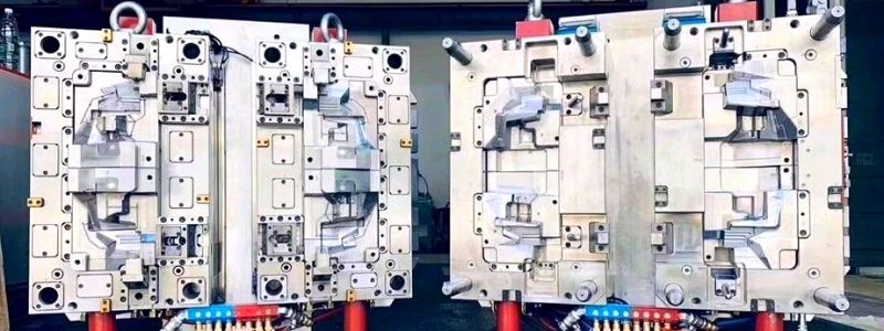
Large injection molds mean high manufacturing costs. Compared with general injection molds, it has larger size and weight. Difficulties in the manufacturing, transportation, and installation of molds. So when designing, we have to combine many factors.
This article is a case study of injection molds for refrigerator transparent cabinets. This is a very classic case.
Analytic of plastic part
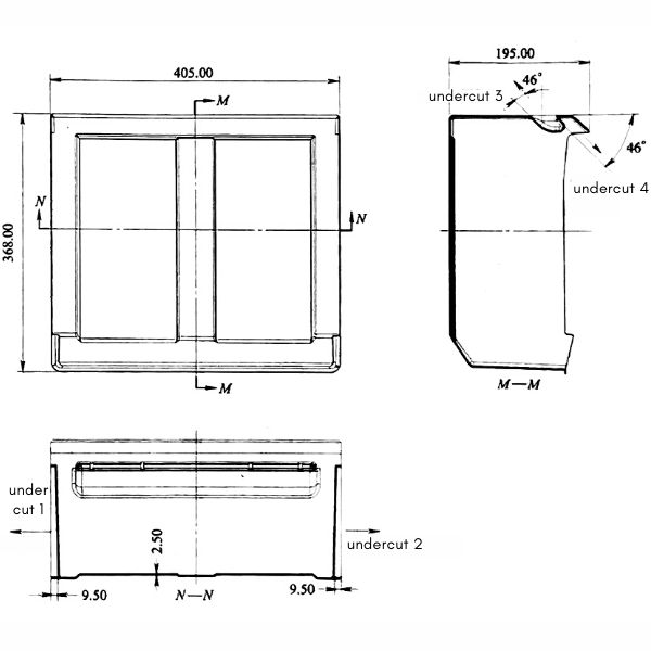
This plastic part belongs to the thin shell box structure. Its surface requirements are very high. Its maximum size is 405mm × 368mm × 195mm, its wall thickness is 2.50mm, and its weight is about 1.1kg. Another characteristic of this plastic part is the complex core-pulling structure. It has a total of 4 undercuts. The undercut -3 and the undercut-4 form an angle of 46 ° with the mold opening direction. This is a difficult point in mold design. The plastic material is transparent PS with shrinkage rate of 0.5%.
Design of mold structure
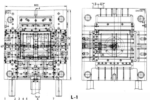
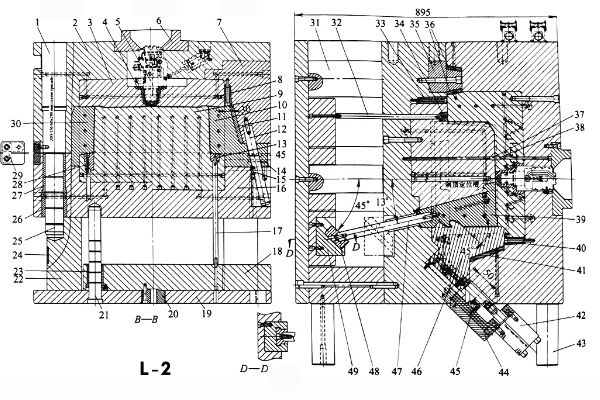
The mold base adopts non-standard mold base. The dimensions are 900mm × 800mm × 895mm. This is already the category of large molds. The detailed structure is shown below.
Gate System
The mold base adopts non-standard mold base. The dimensions are 900mm × 800mm × 895mm. This is already the category of large molds. The detailed structure is shown below.
Formed parts
The forming parts of this mold are composed of inserts 3, 9 and sliders 10, 30, 46 and cam 39. The inserts on both sides of the movable mold adopt the structure of wedge blocks -8,-33. The wedge tightening angle of the wedge block is 3 °. This is to ensure the accuracy of the mold and facilitate the installation and disassemble of large inserts.
Side core-pulling mechanism
1.External core-pulling mechanism
The side core-pulling mechanism of the mold mainly includes four parts: three on the outer side and one on the inner side. Two of the outer cores adopt the conventional structure of “angle pin + slider”. It mainly includes angle pin -12, a slider -10, a locking -7, a stop pin 14, and a positioning ball 15. The other outer core is a “hydraulic cylinder + slider” structure. The parts include a hydraulic oil cylinder 42, a stopper 45, and angle pin 46. Although the cost is increased, the extraction and reset of the oblique slider is stable and reliable.
2.Inner core pulling mechanism
The oblique inner core pulling is the most difficult part of this mold. Since Pulling downward direction 46 °. Conventional cam structures cannot complete this process. Otherwise it will cause severe deformation of the plastic parts. To be able to solve this problem. When designing, the guide groove of the cam base is inclined by 46 °. This structure is simple and reliable. In addition, the inclined top adopts a split structure. It saves material, and is convenient for loading and unloading and maintenance. This part of the structure includes a cam 39, a link bar 47, a small slider 48 and a cam base 49.
3.Large slider
Large molds use large sliders. Compared with ordinary sliders, the movement principle is the same. The inclined angle of the angle pin is 15 ° ~ 25 °. The locking angle is 2-3 degrees larger than that of the angle pin.
The differences are as follows:
1. The angle pin is pulled out differently. See Figure L2 B-B.
2. The shape is different. The center is dug and the sliding surface is processed to lubricate the oil storage tank.
3. It is best to design craft screws on the top of the slider. Easy to process and install.
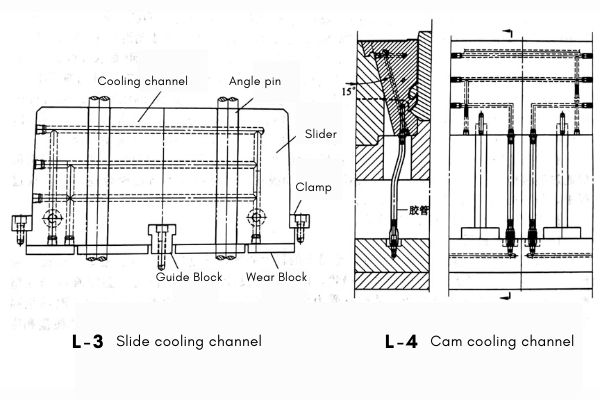
4. Add a central guide block. See picture L3.
5. The larger the safety distance, the better, if there is space. The core drawing distance is generally 8-10mm greater than the depth of the plastic part. ,
6. Be sure to add water to cool. As shown L3.
7. Both sides of the slider must be widened and guided by the quenched pressure block. As shown L3.
8. Be sure to add wear-resistant blocks on all friction surfaces, including the bottom of the slider. As shown L3.
Cooling system
The design of the cooling system directly affects the molding cycle of the mold and the accuracy of the plastic part. This is especially important for large mold cooling systems. The molds use straight-through cooling water channels. Its large number and reasonable location make it a classic.
Part 1
All cooling water channels in the moving and fixed mold inserts are uniformly arranged along the cavity surface. This can be a rapid cooling of the mold. The temperature of each part of the cavity is balanced. Conducive to improving the accuracy and production efficiency of plastic parts.
Part 2
The size of the cam of the mold is large, and the contact area with the melt is large. A large amount of heat is absorbed during molding, and this part of the heat must be discharged in time. Otherwise it will affect the molding cycle. In severe cases, the cam may become stuck. The cam of the mold is sufficiently cooled, as shown in the figure L4.
Part 3
Same as the case of cam. The slider of this mold also needs to be cooled. The layout of the watercourse is shown in the figure L1,L2,L3.
Ejection system
For large transparent thin-walled plastic parts, the ejection system is a difficult point. The ejection system of this mold is composed of stripper bar 13, 28, 34 and high-pressure gas valves 37, 38. The high-pressure gas valve on the fixed mold side is mainly used to blow gas into the cavity when the mold is opened. Prevent the plastic parts from sticking to the surface of the cavity on the fixed mold side. It should be particularly noted that pushing the bottom surface with a ejector pin will leave obvious marks. The push-out effect is very poor, and the plastic parts are easily whitened, deformed, and even worn. The best choice is to use stripper bar and air push.
Guided positioning system
During the working process of the injection mold, the parts will move and rub against each other. The design of the guidance system can ensure the relative position accuracy of the mold and the safety and reliability of the parts. The guide parts of the mold include a movable template guide post 25, a guide sleeve 27, a push rod fixing plate guide post 21, a guide sleeve 23, and a small slider 48, a base 49 and a clamp and a guide block . The positioning parts include a positioning block 35, a stopper pin 14 and a positioning ball 15 of the slider, a stopper 45, and a cone-shaped positioning groove on the cam.
Experience and skills
When designing large molds, you must have a complete set of thinking methods and skills. From the perspective of the force components of the mold, rigidity should be considered. For injection molding, the melt should fill the cavity quickly and orderly. In terms of plastic part quality and production efficiency, the mold should be kept at a constant temperature to speed up the entire heat exchange process.
