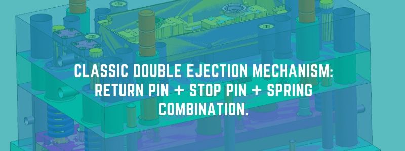
Double ejection is a common method of ejection system. This method is used to form plastic parts with undercut. When the lifter cannot be used and the slider pops up. In order to better ejection the product, or to avoid gate strain. Sometimes in order to meet the automatic ejection of the plastic part, it is necessary to add another ejection action.
Plastic parts analysis.
The following is an example of the structure of double ejection.
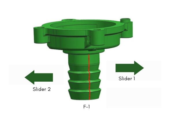
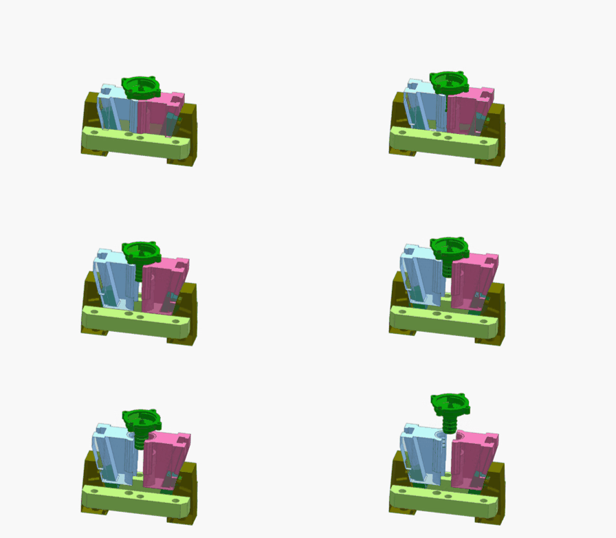
First, analyze the product. As shown in the figure below, there are reverse buckles on both sides of the product. The mold structure adopts 2 inner sliders for core pulling. The reason why the mold uses double ejection is mainly to synchronize the inner slider core pulling and product ejection. The overall structure of the mold is more compact.
Design ideas.
The first ejection is to push open the B plate first, and pull out the inner slider. The second ejection is the ejection of the product with ejector.
How to realize the second ejection action? This structure realizes the second ejection by return pin + stop pin + spring. Understand these three design ideas, it becomes simple to understand the double ejection of this example.
Double ejection structure diagram.
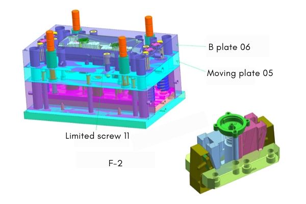
The following is a detailed explanation of the structure. See the figure below for the breakdown of the structural parts.
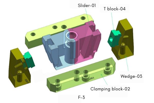
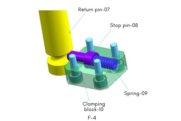
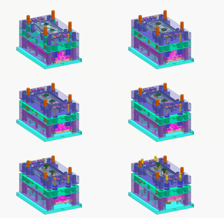
The principle of double ejection.
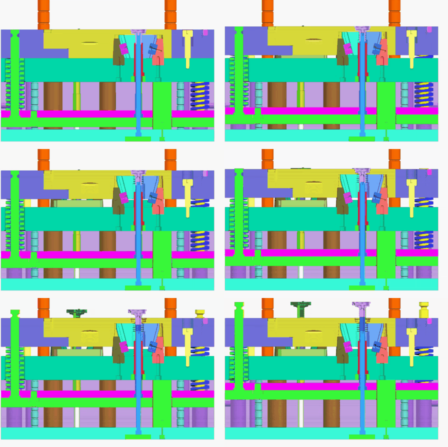
The first ejection.
When the mold starts to eject, the ejector pin returns to pin 07 and pushes the stop pin 08. At the same time, the gear pin pushes the B plate 06 forward together.
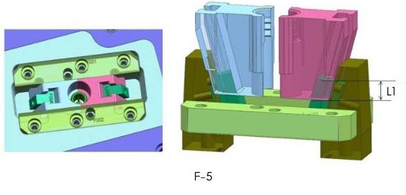
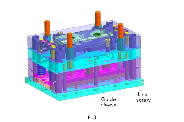
Shovel wedge-03 is fixed on the plate-05. Slider-01 and clamping block-02 are installed on the B plate. When the B plate moves to the distance L1, the slider-01 is disengaged from the product under the drive of the”T” block 04 chute. At the same time, the limit screw starts to stop the B plate move.
The second ejection.
The ejector pin continues to eject. Since the B plate has stopped moving, the return pin forces the stop pin-08 to retract. The return pin passes through the B board to continue ejection. And finally the product is ejected by the ejector pin. Thus, all ejection is completed, and the reset of the B plate is pressed back by the parting surface and the return pin.
How to design the inner slider?
The inner slider, in turn, is viewed from the back, which is the same as the normal slider drawing.
Note: The inner slider cannot be separated from the”T” block. Leave at least 1/3 of the “T” block lock position L 1 inside the inner slider. It is convenient to reset the inner slider when closing the mold. Do not design stopper block for this structure. (As shown below)
How to design return pin and stop pin?
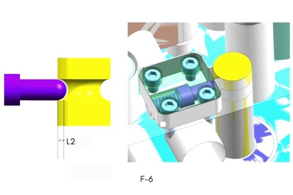
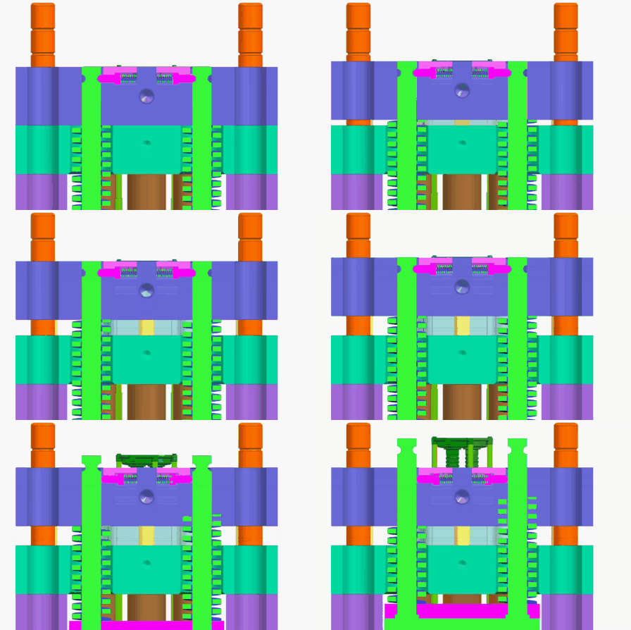
Design a circle of round grooves on the return pin to cooperate with the stop pin (see Figure). The spring 09 is designed to reset the stop pin. The compression stroke of the spring is greater than the L 2 distance, and the spring is in a pre-compressed strong state. The front design of the clamping block 10 is convenient for disassembly and assembly.
Note:
The return pin and stop pin are suitable for mold bases up to 4040. The reason is that the mold base is too large. It may cause the weight of the B plate to directly hit the stop pin, and the secondary ejection effect cannot be achieved.
Notes for the double ejection.
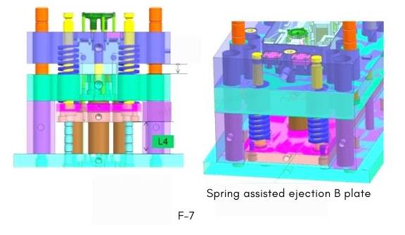
1.The actual ejection distance of the product is the ejection distance of the ejector plate minus the ejection distance of the B plate. That is L 4-L 3. The reason is that the ejector plate and the B plate are in synchronous movement. During this time, the product has not been ejected. (Pictured)
2.B plate needs to add spring to assist ejection, which plays a safety role.
3. When the B board is ejected, a motion guide sleeve needs to be designed. And design limit screws. (Pictured)
In summary.
The key to the double ejection is the ejection sequence. Complete all operations without damaging the product. The second ejection actually reduces the difficulty of forming plastic parts.
Of course, the double ejection mechanism changes according to the structure of the plastic part. The design is more about the details. If you have similar problems with this structure, you may wish to contact us.
