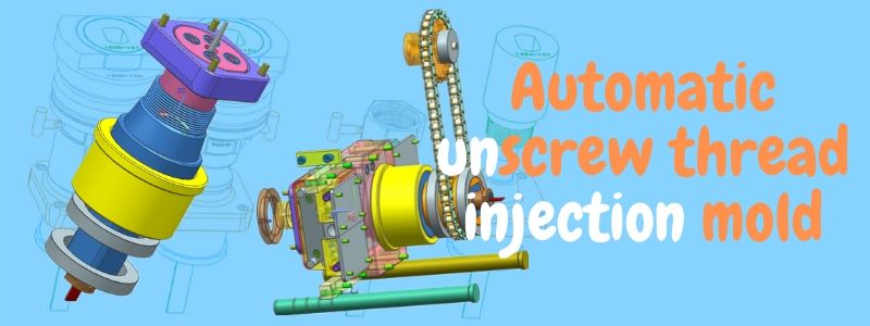
Threaded plastic parts are common. There are two types of threads on the plastic parts: external and internal. The external threads with low accuracy are often eject by a side core pulling mechanism. Internal thread has two structures: forced ejection and automatic unscrew.
The forced ejection must be the following three conditions:
1. Soft glue, such as PVC, PP and PE.
2. The tooth profile is circular, not rectangular, trapezoidal or triangular.
3. The height of the tooth profile is small, and the following formula must be satisfied: (thread large diameter-thread small diameter) / thread small diameter ≤ A. The size of A depends on the plastic type. Generally speaking, PP is 5%, PA is 9%, ABS is 8%, POM is 5%, LDPE is 21%, and HDPE is 6%.
Plastic parts analysis.
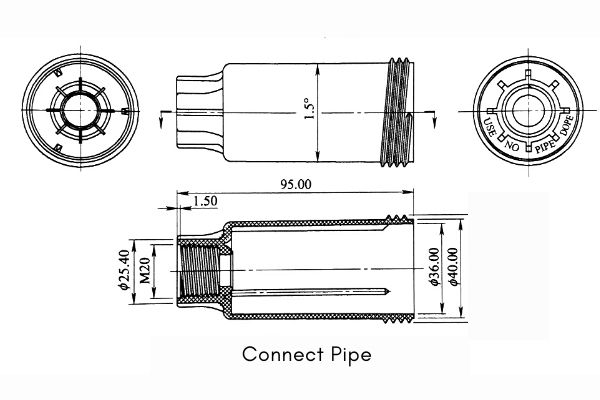
This plastic part is a connect pipe on an mechanical product. The structure and dimensions are shown in the figure. Material of the product is ABS, shrinkage rate is 0.5%. Plastic parts are cylindrical parts. The biggest feature is that there is a continuous thread inside and outside. The internal thread is M20 and the external thread is M44. The teeth are triangular and cannot be ejection forcibly. How to release the mold is the difficult point of mold design.
Mold structure analysis.
No.1
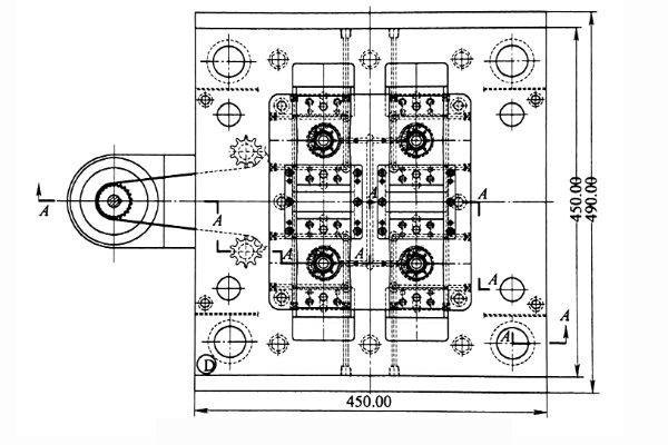
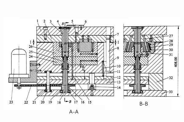
The plastic part is a rotating body. The customer requires 4 cavities. According to the assembly position of the plastic part on the product. The external thread is formed by side core pulling and parting mechanism. The internal thread adopts the “motor ten chain ten sprocket” automatic thread-removing mechanism. The mold base adopts LKM standard two-plate mold base 4545-C1A40-B80. The mold structure is shown in the figure above.
No.2
Due to the structure of the mold, the cavity can only be set longitudinally. The plastic part belongs to the cylindrical rotating body. The gate design is the best choice on the large end face. And set 2 points to feed. The pouring system of the mold is composed of a main flow channel, a flow distribution channel and a gate. Among them, the runner is more complicated, and part of it is on the parting surface of the fixed mold A plate and the movable mold B plate. There is also a part on the lateral parting plane of the two Half sliders 30 and the fixed mold core 3. As shown below.
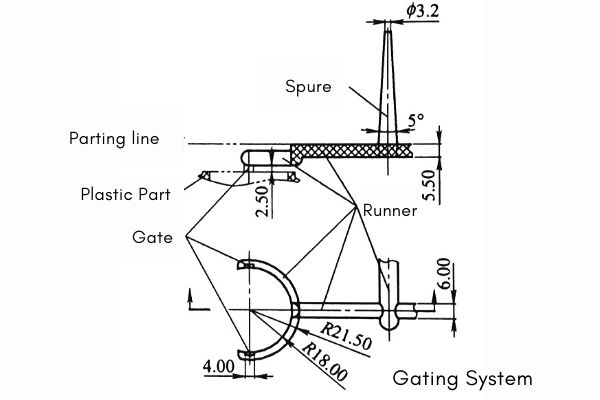
Molded part design.
The movable mold insert adopts a mosaic structure. This is for ease of manufacture and venting of the cavity. Consists of mold insert 24 and 26. Because the two towns are assembled in the moving mold frame. Combined machining methods can be used when machining cavities. The quality at the parting line can be effectively guaranteed. The mosaic structure is also conducive to exhaust. The forming parts of the mold include a fixed mold core 3, movable mold parts 24 and 26, a threaded core 25 and a Half block 30.
Ejection system and unscrew thread mechanism.
No.1
This is the most complex core structure. The automatic thread removal mechanism adopts the structure of “motor ten roller chain ten sprocket ten thread core”. That is, the motor 23 drives the roller chain 22, and the roller chain 22 drives the sprocket 16. The sprocket 16 drives the large sprocket shaft 18 through the key 19. The large sprocket shaft 18 drives the threaded core 25 through a square wedge. See Figure-Mold structure and Figure L1 for details.
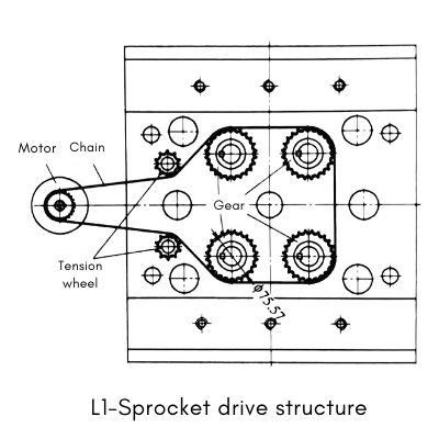
No.2
During the rotation of the threaded core, the reinforcing rib on the outer surface plays a role of stopping rotation. The plastic part will move up and away from the moving model cavity in the axial direction. Finally, the bypass in the gating system is pushed by the ejector pin. The bypass is connected to the plastic part through a gate, and the plastic part is pushed out of the mold. The ejection system of this mold includes a ejector pin 15, a ejector fixing plate 12, a ejector base plate 13, a reset rod 11 and a reset spring 10.
Design of side core pulling mechanism.
Part 1
The side core pulling mechanism is the second largest core mechanism of this mold. It adopts the structure of “Huff slider + block + angle pin + locking block + positioning bead”. See Figure 6-14 for details. Since the mold has 4 cavities, there are 8 sliders. And the core pulling direction of 4 sliders is toward the center of the mold. Therefore, the pressing block of the slider must adopt a mosaic structure, otherwise it cannot be assembled.
Part 2
Sufficient slider stroke must be ensured to facilitate mold release. Generally, the slider stroke is added with a safety value of 1 to 5 mm based on the lateral concave-convex depth. Angle pin and swing levers take smaller safety values. Other types take a larger safety value. However, when this mold uses a Huff mold (also known as a flap clamping mold) to form plastic parts such as outer patterns or coil bobbins, the lateral travel of the slider cannot simply depend on the depth of the undercut, but also on the radius of the side . In this case, the lateral stroke S of the slider can be obtained by the drawing method shown in Fig. L2.
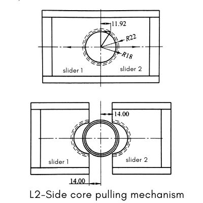
Design of temperature control system.
The temperature control system of the mold directly affects the labor productivity of the mold and the molding quality of the plastic part. Under the premise of not affecting the melt filling, try to achieve rapid cooling and balanced cooling as much as possible. The moving mold side of the mold is mainly cooled by straight-through cooling water pipes. The fixed mold side is mainly cooled by the form of “water well + water pipe”. See Figure 6-12. This cooling method effectively guarantees the molding quality of plastic parts.
The final summary.
The power source for the automatic ejection of the internal thread of the mold is a motor. The transmission method used is “motor ten single-row roller chain + three arc-linear tooth sprocket”. This transmission method has the following advantages.
1.The average transmission ratio is accurate without slippage;
2.Compact structure, low pressure on the shaft;
3.High transmission efficiency, up to 98%;
4.High carrying capacity, up to 100kW;
5.Long-distance transmission is possible;
6.Low cost.
However, there are the following disadvantages.
1.The instantaneous transmission ratio is not constant;
2.The transmission is not stable;
3.Noise and impact during transmission
4.High requirements during installation.
